Completion
Complete each
statement.
|
|
|
1.
|
This is The FOA Online Design Self-Study Program Case Study
No. 6.
An auto manufacturer has many industrial robots in a
manufacturing plant. Each robot is connected to the control room over a duplex fiber optic link using
two fibers. The fiber is chosen for its immunity to electromagnetic interference as the links only
run at 200 kilobits per second. Cables are run to each individual machine and connected to them
inside a small termination box on the side. A conventional patch panel is used in the control
room.
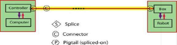
Basic System Information:
This is the
basic layout of a cable system. Each controller is in a remote control room with equipment connected
to the permanently installed cable plant at a patch panel. A cable is run separately to each robot
and terminated inside a box on the side of the base. The controllers use a relativley low speed
connection with 850 nm LED sources. The system operates over MM fiber or PCS fiber.
Please enter your name, CFOT/Membership number and date to begin this
exercise.
|
Multiple Choice
Identify the
choice that best completes the statement or answers the question.
|
|
|
2.
|
The system runs at low speeds
and has been designed over a decade earlier using both multimode graded-index fiber and PCS fiber.
How does that affect the choice of fiber. Which one
of the following multimode fibers are appropriate for this network?
OM1
OM2
OM3
OM4
a. | Any of these fibers will work | b. | Either OM3 or OM4 | c. | Either OM1 or
OM2 | d. | OM1 only |
|
|
|
3.
|
The backbone cable is run
inside the control room and then outside on the factory floor. The company prefers to not run cable
in conduit, but ruggedness is mandatory. They also prefer to minimize hardware for terminations and
splices. What cable type provides the best protection for fibers in premises
installations?
a. | Zipcord | b. | Distribution | c. | Breakout | d. | Loose
tube |
|
|
|
Typical Specifications
Provided for use as case
studies for design labs in FOA courses.
| Component
Specifications | | | | | Fiber
Loss | | | Multimode
at 850 nm | 3.0 dB/km (TIA 568: 3.5 dB/km) | | Multimode at 1300 nm | 1.0 dB/km (TIA 568: 1.5 dB/km) | | | | | Splice Loss | (TIA 568: 0.3 dB, all
types) | | | | | Connector Loss | (TIA 568: 0.75 dB, all types) | | Multimode, adhesive/polish | 0.3
dB | | Multimode,
prepolish/splice | 0.5 dB | | |
| Active Device and System Specifications | | | | | Digital Transceiver Specs1 | Power (dBm), T=transmit, R=receive | | 850 LED | T: -15 dBm, R: 0 > -25
dBm | | |
Link margin specifications for most
standardized fiber optic networks are on the FOA Tech Topics Site
(http://www.thefoa.org/tech/Linkspec.htm). It should be used as a reference for designers and for the
courses.
|
|
|
4.
|
Using the information supplied above, assuming the component
specifications are per TIA standards, calculate the cable plant loss budget for a 200m link,
including the loss of the patchcords.
a. | 2.95 dB | b. | 1.50
dB | c. | 0.90 dB | d. | 2.11
dB |
|
|
|
5.
|
Using the information supplied above, assuming the component
specifications are typical values and connectors are adhesive/polish types, calculate the cable plant
loss budget for this link.
a. | 2.95 dB | b. | 1.50 | c. | 0.90 | d. | 2.11 |
|
Multiple Response
Identify one
or more choices that best complete the statement or answer the question.
|
|
|
6.
|
What parameters should be tested and documented to confirm
proper installation?
|
|
|
7.
|
Testing of each fiber in the cable should be done as
follows:
(Choose all the correct answers)
|