Completion
Complete each statement.
|
|
|
1.
|
This is The FOA Online Design Self-Study Program Case Study No. 10.It may also
be used for a design lab in a CFOS/L course. This exercise covers the design of an Optical LAN
(OLAN) premises network A large organization has decided to install an optical LAN using POL
(passive optical LAN) architecture because of its cost and power savings. POL OLANs use technology
similar to FTTH PONs (passive optical networks) in MDUs (multi-dwelling units). A typical link is
shown below. Use common OLAN/ FTTH PON design parameters to design this system. Premises OLAN
POL: 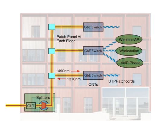 Basic System Information: | Segments | Length | Details | | OLT to PON Splitter | 50-500m | Multi-fiber SM cable, SC-APC connectors | | PON Splitter to ONT switch | 125 - 1500 m | SC-APC
connector at POL splitter, patch panel at each floor | | ONT Switch | | SC-APC connector | | PON Splitter | | 32 port | | | |
| GPON System | Transmitter Wavelength | Operating Loss Range | | Downstream Digital | 1490 nm | 13-28 dB | | Upstream Digital | 1310 nm | 13-28 dB | | | |
Please enter your
name, CFOT/Membership number and date to begin this exercise.
|
Multiple Choice
Identify the choice that best completes the statement or
answers the question.
|
|
|
2.
|
Which one of the following fibers is the best choice for this OLAN network?
a. | OS1/OS2 or ITU G.652 - single-mode NDSF (non-dispersion-shifted
fiber) | b. | ITU G.653 - single-mode dispersion-shifted optical fiber | c. | ITU G.654single-mode
fiber which has the zero-dispersion wavelength around 1300 m wavelength | d. | ITU
G.655single-mode NZ-DSF (nonzero dispersion-shifted) fiber), optimized for WDM and
long-distance cable runs |
|
|
|
3.
|
The multi-fiber cable for the backbone from the PON splitter to the patch panel
at each floor will be placed in plenum-rated innerduct. The cable design best for that section of the
link is a ______ design and the cable must be _____.
a. | Loose tube, water blocked | b. | Distribution, rated for flame
retardance | c. | Ribbon, flexible | d. | Simplex, yellow |
|
|
|
4.
|
The cable chosen for the section to the OLT 4-port switch only needs to be _____
.
a. | Simplex | b. | Zipcord | c. | Distribution 2
fibers | d. | Any of the above |
|
|
|
5.
|
Short SM cable runs typical of OLANs makes it important to use ____ connector
styles to prevent ______.
a. | LC, patching | b. | SC, damage | c. | UPC,
loss | d. | APC polish, reflectance |
|
|
|
6.
|
How many fibers are required to connect each switch at the user work
area?
a. | One | b. | Two | c. | Four | d. | As many as
possible |
|
|
|
7.
|
In order to calculate a link power budget to ensure the system will work
on the cable plant being designed, it is necessary to have what information on the communication
system intended for use on the cable plant?
a. | Wavelength | b. | Transmitter and receiver power
requirements | c. | PON splitter ratio and excess loss | d. | All of the
above |
|
|
|
Typical Specifications
Provided for use as case studies for design
labs in FOA courses. | Component Specifications | | | | | Fiber Loss | | | Singlemode at 1310 nm | TIA 568: 1
dB/km (premises), (0.4 OSP) | | Singlemode at
1490/1550 nm | TIA 568: 1 dB/km (premises) (0.25 OSP) | | | | | Splice Loss | TIA 568:
0.3 dB, all types | | Singlemode, fusion | 0.05
dB | | Singlemode, mechanical | 0.3
dB | | | | | Connector Loss | TIA 568: 0.75 dB, all
types | | Singlemode, prepolish/
mechanical splice | 0.5 dB | | Singlemode, fusion
splice-on (SOCs) | 0.3 dB (also use for fusion spliced pigtails) | | | | | POL Splitter | Typical Loss (not including connectors on spitters) | | 2 | 4 dB | | 4 | 7dB | | 8 | 11 dB | | 16 | 15 dB | | 32 | 19 dB | | |
Link margin specifications for most standardized fiber optic
networks are on the FOA Tech Topics Site (http://www.thefoa.org/tech/Linkspec.htm). It should be used
as a reference for designers and for the courses.
|
|
|
8.
|
Calculate the cable plant loss budget for this link. The links will use 32 port
splitters. Connectors are field installed prepoished/splice connectors. Use the infomation in the
"Typical Specifications" narrative above.
Here is the cable layout for calculating
the loss budget:
(OLT)
CC---25m---CC--SPLITTER--CC--------125m----CC(PATCH PANEL)----50m-----CC
(ONT)
CC=connection
--- = fiber
The total loss should be _____ .
a. | 19.0 dB | b. | 20.70 dB | c. | 21.70
dB | d. | 22.95 dB |
|
|
|
9.
|
Calculate the cable plant loss budget for this link if instead of
prepoished/splice connectors it used fusion-spliced pigtails. The links will use 32 port splitters.
Use the infomation in the "Typical Specifications" narrative above.
Here is the
cable layout for calculating the loss budget:
(OLT)
CC---25m---CC--SPLITTER--CC--------125m----CC(PATCH PANEL)----50m-----CC
(ONT)
CC=connection
--- = fiber
The total loss should be _____ (the exact number is
one of the answers)
a. | 19.0 dB | b. | 20.7 dB | c. | 21.7
dB | d. | 22.95 dB |
|
|
|
10.
|
A similar OLAN system using GPON is being installed in a college campus. The OLT
will be in a central facility and a fiber will run to each building where the splitter will be
installed (there may be multiple splitters in a building depending on the number of users.)
Calculate the cable plant loss budget for this link if instead of prepoished/splice connectors it
used fusion-spliced pigtails. The links will use 32 port splitters. Use the infomation in the
"Typical Specifications" narrative above.
Here is the cable layout for calculating
the loss budget:
(OLT)
CC---200-800m---CC--SPLITTER--CC--------25-125m----CC(PATCH PANEL)----50m-----CC
(ONT)
CC=connection
--- = fiber
Calculate the minimum and maximum loss on a link
using the range of distances shown. Use the premises cabling conservative 1dB/km atttenuation
coefficient for the fiber. Round off to the nearest 0.01dB
The total loss should be _____ to
________ (the exact number is one of the answers)
a. | 19.0 - 21.0 dB | b. | 20.77-21.43 dB | c. | 21.7-22.48
dB | d. | 22.95-25.0 dB |
|
|
|
11.
|
For the GPON equipment listed above, will the systems operate on the planned
cable plant?
a. | Yes | b. | Yes, but may require an attenuator at the
transmitter end | c. | Yes, bmay require an attenuator at the receiver end | d. | No, it cannot
work |
|
|
|
12.
|
The customer has a remote location that is also being considered to be added to
this network. Considering the loss budget above, approximately how far away could a remote locatio be
and still use the same network equipment? (Use the OSP fiber loss: 0.4 dB/km)
|
|
|
13.
|
What parameters should be tested and documented on this GPON system cable plant
to confirm proper installation and compare the loss to the calculated loss budget?
a. | Insertion Loss at any one wavelength | b. | Insertion Loss at 2 wavelengths in the
proper direction | c. | Downstream OTDR traces from CO to subscriber | d. | Upstream OTDR traces
from subscriber to CO |
|
Multiple Response
Identify one or more choices that best complete the
statement or answer the question.
|
|
|
14.
|
What should be included in the design documents to have the customer prepare for
restoration in case of an outage?
|
|
|
15.
|
Cables for OLANs should bend insensitive SM fiber because
___________.
|
|
|
16.
|
OLANs based on PONs can place the PON spliters in any location along the
cable plant and even cascade splitters, e.g. a 4 port splitter near the OLT and an 8 port splitter
near users. The major reason to do this is a design that places splitters close to users or a cascade
design __________. (2 correct answers) 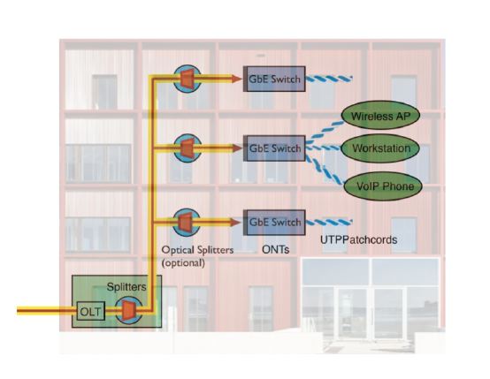
|
|
|
17.
|
Based on the classroom curriculum and the case studies for POLs using GPON
above, which of the following conculsions are correct?
|