Lesson:
Terminating Optical Fiber With A Mechanical Splice
Connector
Objectives:
From this lesson you should learn:
How to use these tools to strip cable to the bare fiber
Tools:
Safety Glasses
Fiber Stripper
Kevlar Shears
Fiber Cleaver
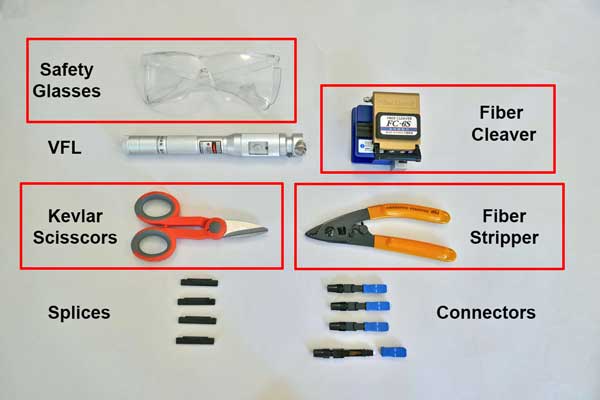
Components:
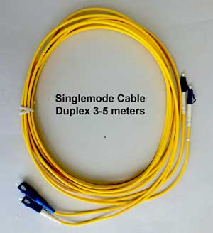
Fiber optic cable
Connectors (several for practice)
Safety:
 |
Always
wear safety glasses when doing any of
these exercises and dispose of all fiber
scraps properly.
Safety
Rules - Read before beginning any
exercises.
|
Exercise
Before attempting this exercise, you should complete
the exercises on stripping
and cleaving
fibers.
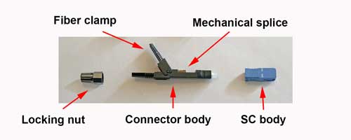
1: Examine the mechanical splice connector. The
connector has a short fiber cemented into the ceramic
ferrule and polished in a factory. Behind the ferrule is
a mechanical splice ready to use and a connector body
that can clamp onto a 900 micron buffered optical fiber
and/or 3mm jacketed cable.
The installation process involves preparing a fiber,
inserting the fiber in the splice section of the
connector, inserting it until it butts up against the
connector fiber to create a splice, then closing the
connector body clamping the fiber (and cable if
terminating a jacketed cable.) Finish
the connector by screwing on the locking nut.
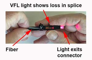
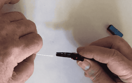
A VFL can be used to verify the splicing process as you
can see below. Insert the connector of your cut
patchcord in the VFL and turn the VFL on. The light from
the end of the fiber will help you see the small hole on
the end of the connector where you must insert the fiber
and it will help you verify the splice in the connector
has been made properly as you can see in the video
below.
We'll use this mechanical splice connector to
terminate the bare fiber end of your cable in this
exercise, first with 900 micron buffered fiber then
with a 3mm jacket cable.
First
with 900 micron buffered fiber
1. Slip the locking nut on the cable's cut end. Makes
certain it is in the correct direction.
2. Use the fiber stripper to cut off
4" (100mm) of the cable jacket and pull off the cut piece.
3. Use the kevlar scissors to cut the aramid fiber
strength members at the end of the jacket, exposing the
900micron tight buffered fiber.
4. Use the fiber strippers to strip ~1.5" (40mm) from the
end of the fiber in 4-6 steps, about 1/4-3/8" (6-8mm) at a
time.
5.
Clean the fiber with a lint-free wipe and alcohol.
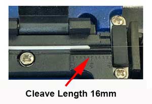
6. Cleave the fiber to a length of 16mm from the end
of the 900 micron buffer using the cleaver's stripping
gage.
Clean
up all your fiber scraps immediately after cleaving
the fiber and dispose of them in a container like a
used take-out coffee cup marked "Fiber Scraps"!
7. Insert the fiber into one end of the splice on the
connector until it stops and verify the splice is properly
made with the VFL - the light from the splice should be
minimized and the protective cap on the connector should
light up brightly - see the photo above showing
termination with the VFL. You can pull the fiber back
slightly and push it back in, rotating it slightly, if
needed to get a good splice. Then push down the plastic
crimp lever on the connector to hold that fiber. Screw on
the plastic nut to lock the fiber in place.
Watch this to see how it's done:
8. Practice this exercise several times with the
connectors supplied. Be sure to keep several connectors if
you need to do demonstrations to your instructor.
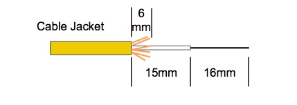
10. Terminating 3mm Cable
Terminating 3mm cable is similar to the 900 micron
fiber steps above. The difference is how the cable is
prepared. The length of 900micron buffered fiber beyond
the jacket and the length of aramid fiber need to be
different. See the stripping diagram below:
Insert the fiber into the connector and watch the
VFL light to ensure a good splice. Close the fiber clamp
on the cable and secure with the locking nut.
You have successfully completed this exercise when
you have made several connectors that show low splice
loss and good light through the connector.
After successfully terminating fiber with
the connector several times, fill in your Scorecard.
Return
to Lesson Plan
This information is
provided by The Fiber Optic Association, Inc. as a
benefit to those interested in teaching, designing,
manufacturing, selling, installing or using fiber optic
communications systems or networks. It is intended to be
used as an overview and/or basic guidelines and in no
way should be considered to be complete or
comprehensive. These guidelines are strictly the opinion
of the FOA and the reader is expected to use them as a
basis for learning, as a reference and for creating
their own documentation, project specifications, etc.
Those working with fiber optics in the classroom,
laboratory or field should follow all safety rules
carefully. The FOA assumes no liability for the use of
any of this material.
|