Lesson:
Building and Testing A Fiber Optic Link - Part 2 - Passive Optical Network (PON) Link
Objectives:
From this lesson you should learn:
How to build a fiber optic link as used in passive
optical networks (PON) using media converters and splitters
Testing the fiber optic link
Components
Safety Glasses
Visual Fault Locator (VFL) or the VFL in the power meter
if it has one
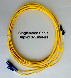
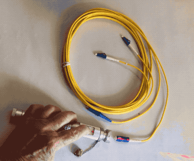
Fiber optic
cable - singlemode with SC connectors, 2 or more
SC connector mating adapters, 4 or more
Fiber Optic Media Converters
Media converters are special fiber optic transceivers used to
convert from one type of cable (the media) to another, typically from
copper cables to fiber optics, although some media converters will
convert from one fiber type to another, e.g. multimode to singlemode.
The FOA Guide has a page about media converters you should read before beginning this exercise.
Exercise 2 uses media converters
that connect over one fiber while still providing full-duplex
(simultaneous) communications bidirectionally over the one fiber. The
one fiber bidirectional links are similar to those used in passive
optical networks (PONs) used in FTTH (fiber to the home) and optical
LANs, so Exercise 2 includes an option to build a PON demonstration.
Media converters are available for purchase online at very
reasonable prices. The exercises show how to use media converters that
use Ethernet protocols to allow connecting computers to the Internet.
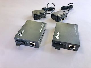
Typical media converters
2
singlemode bidirectional fiber
media converters- you will be using singlemode
fiber
cables from the installation exercises to connect
them. If you plan to do both exercises, you will need 2 sets of media
converters, one set that operates over two fibers and one set that
operates over a single fiber bidirectionally.
You will
connect them over 2 or 4 fiber optic cables used in the other exercises
Also
you need two
Cat 5e patchcords to connect your computer and
router to the media converters. Purchase these online if you do not have
any.
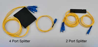
PON Splitters
You will need one or more PON splitters, also available online. Order a
"1 X 2" ( 2port) and a "1 X 4" (4 port) splitter with SC connectors.
Fiber Optic Power Meter
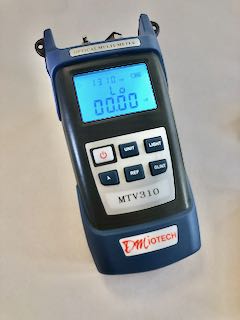
This fiber optic power meter measures in dBm and W and
has a dB range for loss measurements.
It has adapters for SC connectors and any connector with
2.5mm ferrules.
Connecting With The Link You Build
To connect with the link, you need an Ethernet
connection to the Internet and a device that can connect
to the Internet over Ethernet on UTP Cat 5 cable..
Your Internet connection should have a router with
Ethernet ports which can be used.
If you have a computer with an Ethernet port, that will be
ideal for completing the link. You can also use a WiFi
access point connected to your router over UTP Cat 5e
cable for the exercise.
Safety:
 |
Always
wear safety glasses when doing any of
these exercises and dispose of all fiber
scraps properly.
Safety
Rules - Read before beginning any
exercises.
Do
not look directly into the light from the
visual fault locator - it's bright!
|
Exercise
Watch the FOA YouTube Video Of This DIY PON Link Demo Exercise
Before you start, review the use of fiber optic media
converters from the FOA
YouTube video on media converters, the
FOA Guide page on media converters or the Fiber
U MiniCourse on media converters.
You shouls also review the FOA Guide page on FTTH PON Architectures as you will be building a simulated PON network.
Check Your Cables
1: Attach
your cables to the Visual Fault Locator (VFL)
2. Turn the VFL on and ensure the light travels through
the fiber. You can see how bright the glow is at the end
of the fiber, diffused through the fiber protective cap.
This shows how fiber transmits light by total internal
reflection as you learned in the lesson on optical fiber.
Repeat for all the cable you are using in this exercise.
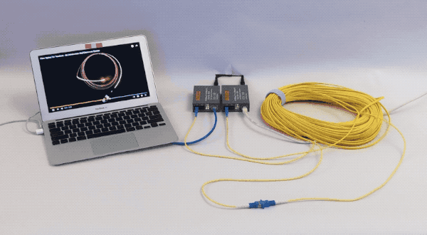
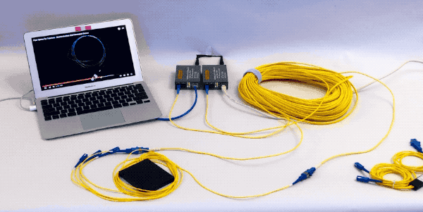
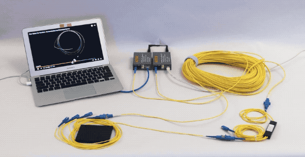
Build A Fiber Optic Link
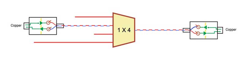
Exercise 1 uses media converters that connect over one fiber like FTTH (fiber to the home) PON (passive optical network) fiber optic links.
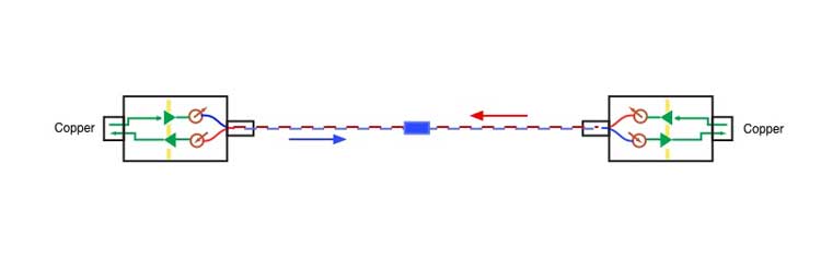
This link uses two media converters that convert
Ethernet
on Cat 5 to fiber optics and transmit
bidirectionally on one singlemode fiber. The diagram above is the link
we
will build.
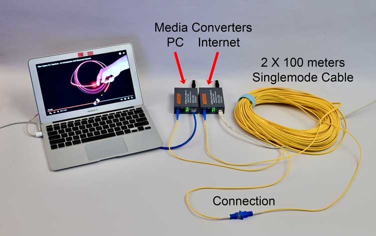
1. Assemble the equipment you need.
2. Power up the media converters and confirm the power
light.
3. Connect
the two media converters with the singlemode cables, 2
cables connected with mating adapter in the middle as shown in the diagram above. Did your link show
the link connection light?
4. Connect your Ethernet devices to the link with UTP Cat
5e cables and confirm the link transmits data. You can
check the indicator lights to ensure the bottom light is
flashing which shows data is being transmitted.
Confirm your is link transmitting data, connecting our laptop
to the Internet over fiber optics, by downloading several websites. This is an FOA YouTube video.
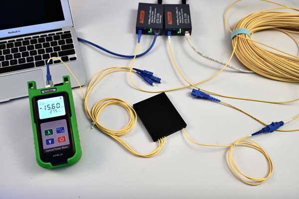
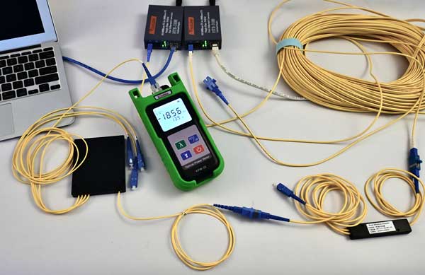
You can open the connection and check the power in both directions from each media converter's transmitter.
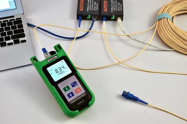
Here are our test results:
We measured -8.34 dBm "downstream" and -12.40 dBm upstream.
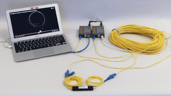
Insert a 2-port passive fiber optic splitter:
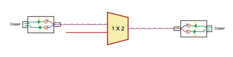
<<<<<<<
Downstream--------------------------------------------------Upstream>>>>>>>>>>
(In a FTTH PON network, the subscriber's ONT (optical network terminal
simulated by one media converter and the PC) would be on the left and
the OLT (optical line terminal) at the head end or central office would
be at the right of our page, simulated by the other media converter.
That makes signals moving downstream moving to the left and upstream to
the right. We
will use that orientation throughout this exercise.)
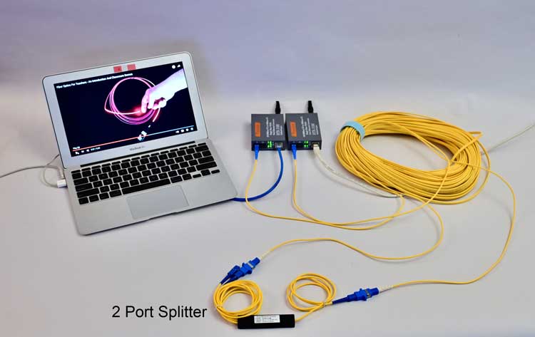
Open the connection in the setup and insert a 2 port (1X2) splitter.
Connect one of the cables to the single fiber side and one fiber to the
two fiber side. Here is how that link now looks:
The splitter takes one fiber input and splits it into two outputs, and
in the opposite direction takes signals from either of the two fibers
and transmits it to the single fiber, so it splits the signal in one
direction and combines the signals in the opposite direction. Thus our
bidirectional link should work through the splitter.
Confirm the link still works.
To prove the splitter sends the same signals out of each of the outputs,
change your connection on the 2 fiber side to the other fiber output of
the splitter and confirm the link still works.
Since the splitter divides the signal into 2 parts, the optical power of
the signal is cut in half (a loss of 3 dB) plus some additional loss
for the inefficiency of the splitter. Measure the downstream loss of the splitter
as follows:
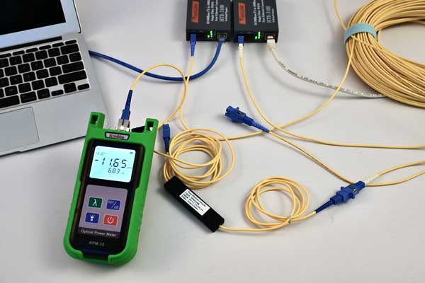
Disconnect the incoming fiber on the input (one fiber) side of the
splitter and measure the output of the cable (not the input of the
splitter) and record that value. Meter set for dBm, 1310 nm, reading
_____dBm.
Disconnect the fiber on the output of the splitter and measure the output of both fibers, Meter set for dBm, 1310 nm, reading _____dBm on one fiber and _____dBm on the other fiber.
How much loss do you see on the splitter? How much difference is there between the two fibers?
Here are our test results:
We measured -11.92 dBm from
output 1 and -11.70 dBm from output 2. Since the input was measured at
-8.34 dBm, the loss was -3.58 dB for output 1 and -3.36 dB for output 2,
about what we expect from a 2 port splitter.
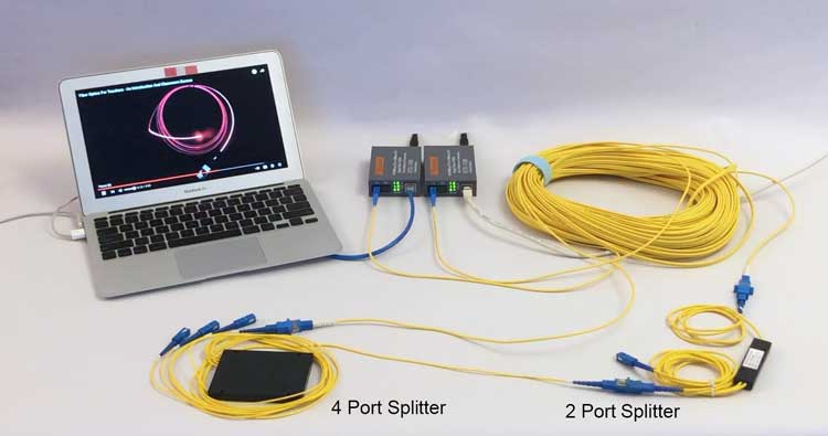
Insert a 4-port (1X4) passive fiber optic splitter:
Remove the 2-port (1X2) splitter and insert a 4 port splitter. Connect one of the cables to the single fiber side and one fiber to the four fiber side.
<<<<<<<
Downstream--------------------------------------------------Upstream>>>>>>>>>>
Here is how that link now looks:
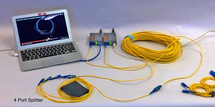
Confirm the link still works.
To prove the splitter sends the same signals out of each of the outputs,
change your connection on the 4 fiber side to the other fiber outputs of
the splitter and confirm the link still works.
Since the splitter divides the signal into 4 parts, the optical power of
the signal is cut in one-fourth (a loss of 6 dB) plus some additional loss for the
inefficiency of the splitter. Measure the downstream loss of the splitter as
follows:
Disconnect the incoming fiber on the input (one fiber) side of the
splitter and measure the output of the cable (not the input of the
splitter) and record that value. Meter set for dBm, 1310 nm, reading
_____dBm.
Disconnect the fiber on the output of the splitter and measure the output of all 4 fibers, Meter set for dBm, 1310 nm,
Fiber 1 reading _____dBm .
Fiber 2 reading _____dBm .
Fiber 3 reading _____dBm .
Fiber 4 reading _____dBm .
How much loss do you see on the splitter? How much difference is there between the 4 fibers?
Here are our test results:
Fiber 1 reading -15.78 dBm, 7.44 dB loss,
Fiber 2 reading -15.55 dBm, 7.21 dB loss .
Fiber 3 reading -15.60 dBm, 7.26 dB loss .
Fiber 4 reading -15.59 dBm, 7.25 dB loss
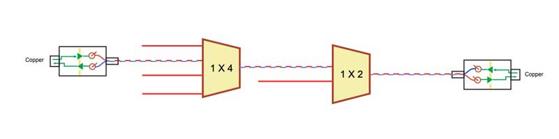
Cascade Splitters Like A FTTH PON Network
FTTH PON networks often cascade splitters to optimize the use of fiber
in the network. Let's simulate a FTTH PON network with 2 levels of
splitting using the 2-port and 4-port splitters we used above. Connect
you setup like this:
<<<<<<<
Downstream--------------------------------------------------Upstream>>>>>>>>>>
And the equipment setup looks like this:
Confirm the link still works.
To prove the splitter sends the same signals out of each of the outputs,
change your connection on the 4 fiber side to the other fiber outputs
of
the splitter and confirm the link still works. You may also want to
change the 4-port splitter connection to the other output of the 2-port
splitter.
Since the splitters divides the signal into 8 parts (1X2 plus 1X4 equals 1X8), the optical power of
the signal is cut in one-eighth (a loss of 9 dB) plus some additional loss for the
inefficiency of the splitter. Measure the downstream loss of the splitter as
follows:
Disconnect the incoming fiber on the input of the 2 port splitter and measure the output of the cable (not the input of the
splitter) and record that value. Meter set for dBm, 1310 nm, reading
_____dBm.
Then measure the power on the output of the 4 port splitter on any of the 3 unused fibers and measure the power there:
Meter set for dBm, 1310 nm, reading
_____dBm.
How much loss do you measure across the two cascaded splitters? ______ dB.
Here are our test results:
Fiber 1 reading -18.83 dBm, 10.49 dB loss,
Fiber 2 reading -18.56 dBm, 10.22 dB loss .
Fiber 3 reading -18.61 dBm, 10.27 dB loss .
Fiber 4 reading -18.56 dBm, 10.22 dB loss
You
have successfully completed this exercise
when you have built a fiber optic link using
the media converters and used it to transmit
data in a simulated FTTH PON network. You also should have tested the power
in the link and the loss of the cable
plant.
Note:
Actual FTTH PONs use special protocols to allow multiple ONTs on the
output of splitters. This involves addressing each uniquely and
encrypting data to ensure the privacy of each user. The media converters
here do not have FTTH PON type protocols to allow using multiple media
converters on this simulated network. See the FOA Guide for more
information on FTTH PON Networks.
Complete the exercise and fill in your Scorecard.
Return
to Lesson Plan
This information is
provided by The Fiber Optic Association, Inc. as a
benefit to those interested in teaching, designing,
manufacturing, selling, installing or using fiber optic
communications systems or networks. It is intended to be
used as an overview and/or basic guidelines and in no
way should be considered to be complete or
comprehensive. These guidelines are strictly the opinion
of the FOA and the reader is expected to use them as a
basis for learning, as a reference and for creating
their own documentation, project specifications, etc.
Those working with fiber optics in the classroom,
laboratory or field should follow all safety rules
carefully. The FOA assumes no liability for the use of
any of this material.
|