True/False
Indicate whether the statement is
true or false.
|
|
|
1.
|
Fiber optic inspection microscopes can focus the light in a fiber into the eye
creating potentially harmful power levels.
|
|
|
2.
|
Angular or oblique inspection (from the side) of a fiber optic connector
provides a better view of the finish of the end of the connector’s ferrule.
|
|
|
3.
|
New fiber optic cables in their orignal packaging with dust caps on the ferrules
do not need inspection and claning before use.
|
|
|
4.
|
When measuring optical power, relative power like when measuring loss is
expressed ad dB, while absolute power is measured in dBm.
|
|
|
5.
|
Power budget and loss budget are the same thing.
|
Multiple Choice
Identify the choice that best
completes the statement or answers the question.
|
|
|
6.
|
Fiber optic connectors can be cleaned by several methods. Which one usually
gives the best results.
a. | Wet | b. | Dry | c. | Wet-to-dry | d. | Just rub it on your
shirt |
|
|
|
7.
|
A dB change of 10 dB means power has changed by a factor of
_________.
|
|
|
8.
|
When measuring optical loss from a 0dB reference, a power meter will display
loss as a _________.
a. | Positive number | b. | Negative number | c. | Decimal
value | d. | Watts |
|
|
|
9.
|
To measure absolute optical power in dBm on an optical power meter, you need to
know the _________ to calibrate the power meter.
a. | Power level | b. | 0 dB level | c. | Source
wavelength | d. | NBS standard |
|
|
|
10.
|
If you measure a 10 milliwatt source with a power meter calibrated in dBm, the
meter should read ___________.
a. | + 10 dBm | b. | - 10 dBm | c. | 0
dBm | d. | 10 dB |
|
|
|
11.
|
Consider the cable plant shown here:  If the fiber
loss is 3dB/km, connection losses are 0.5dB each and splices are 0.3 dB each, what is the loss
of the cable plant on this link. a. | 3.3dB | b. | 4.3dB | c. | 2.85dB | d. | 3.3dBm |
|
|
|
12.
|
Consider the cable plant shown here: 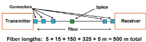 The fiber
loss is 3dB/km, connection losses are 0.5dB each and splices are 0.3 dB each. .The transmitter
output is -5dBm and the receiver requires at least -10dBm. Will the link work on this cable
plant. a. | No | b. | Yes | c. | Depends on the
wavelength | d. | Depends on the fiber |
|
|
|
13.
|
When you test a splice in the cable plant and it shows a “gainer”,
it should show _______ when tested in the opposite direction.
a. | No loss | b. | Gain also | c. | More loss than the
actual splice loss | d. | The correct splice
loss |
|
Multiple Response
Identify one or more choices
that best complete the statement or answer the question.
|
|
|
14.
|
Visual fault locators all one to visually find faults like cable stress and
connector or splice loss because _______. (Check all answers that are true.)
|
|
|
15.
|
OTDRs are used with launch and receive cables in order to __________.(More than
one answer may be true.)
|
Matching
|
|
|
Match the instrument to the test performed: a. | Inspection
microscope | b. | Visual Fault Locator | c. | Optical Power Meter | d. | Light source and
power meter (OLTS) | e. | OTDR |
|
|
|
16.
|
Testing installed cable plant
|
|
|
17.
|
Measuring cable plant length
|
|
|
18.
|
Finding cable breaks caused by dig-ups
|
|
|
19.
|
Verifying splice loss in a concatenated cable
plant
|
|
|
20.
|
Checking connector cleanliness
|
|
|
21.
|
Finding stress/bending losses or breaks near the end of
cables
|
|
|
22.
|
Measuring transmitter or receiver power in a link
|
|
|
23.
|
Testing patchcords
|
|
|
When mesuring insertion loss, there are 3 methods to set a “0dB
refrence.” Why are there 3 methods and what is the difference in loss measured with the 3
methods? 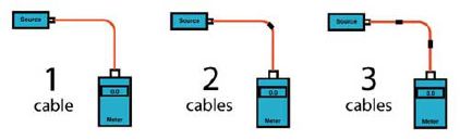 a. | One cable
reference | b. | Two cable reference | c. | Three cable
reference |
|
|
|
24.
|
Used for standard connectors when they do not match the connectors on the test
equipment
|
|
|
25.
|
Used for standard connectors when they match the connectors on the test
equipment
|
|
|
26.
|
Used for plug/jack connectors like MPO or MIL multipin connectors
|
|
|
27.
|
Test results will show lower loss because one connection is included in
reference
|
|
|
28.
|
Test results will show lowest loss because two connections are included in
reference
|
|
|
29.
|
Preferred reference method for most tests
|