Completion
Complete each statement.
|
|
|
1.
|
This is The FOA Online Design Self-Study Program
Case Study No. 9.
Metropolitan Data, Traffic Control and CCTV Surveillance System
A
medium-sized town is planning to install a metropolitan system connecting government buildings,
implementing a smart traffic control system and installing a number of video cameras around the town.
All systems connect to a central monitoring and recording facility. Distances are large enough that
fiber is needed and networking equipment, traffic control equipment and cameras with fiber interfaces
are ordered. Due to security concerns, all cable must be placed in conduit. A typical video
link is shown below
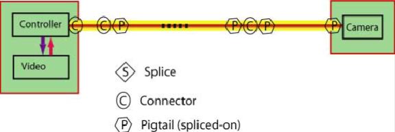 
Basic System
Information:
The maximum fiber/cable distance is 25 km but various links are in the range of 0.5
to 25 km. The cable is underground in ducts and fusion spliced at transition points, plus 2
pigtails are spliced on the ends for termination.
Refer to each question for details of
specific links used in the question.
Please enter your name, CFOT number (if
applicable) and date to begin this exercise.
|
Multiple Choice
Identify the choice that best
completes the statement or answers the question.
|
|
|
2.
|
The CCTV video system runs at low speeds but over
relativley short distances appropriate for a metropolitan area using singlemode fiber.
What will be the wavelength used for
transmission?
A. | 1310 nm | B. | 1490 nm | C. | 1550
nm | D. | 1310 and 1550 nm |
|
|
|
3.
|
The system will use fibers already installed in
conduits underground if the fibers are appropriate. Which one of the following fibers are appropriate
for this network?
ITU G.652
ITU
G.653
ITU G.654
ITU
G.655
A. | Any of these fibers will work since the link is
short | B. | Only non-zero dispersion shifted
fiber | C. | Only low water peak fiber | D. | Only cutoff shifted fiber |
|
|
|
4.
|
In order to ensure the system will work on the
cable plant being designed, it is necessary to have what information on the communication system
intended for use on the cable plant?
A. | Wavelength | B. | Transmitter min/max power output | C. | Receiver min/max input powers | D. | All of the above |
|
|
|
Typical Specifications
Provided for use
as case studies for design labs in FOA courses.
| Component
Specifications | | | | | Fiber Loss | | | Singlemode at 1310 nm | 0.4 dB/km (TIA 568: 1 dB/km) | | Singlemode at 1550 nm | 0.25 dB/km | | | | | Splice Loss | (TIA 568: 0.3 dB, all
types) | | Singlemode, fusion | 0.05 dB | | Singlemode,
mechanical | 0.3 dB | | | | | Connector Loss | (TIA 568: 0.75 dB, all
types) | | Singlemode, adhesive/polish | 0.3 dB | | |
| Active Device and System Specifications | | | | | Digital Transceiver Specs1 | Power (dBm), T=transmit, R=receive | | 1310 laser (>1
Gb/s) | T: +3 to -3 dBm, R: -15 > -25 | | |
Link margin specifications for most standardized fiber optic networks are
on the FOA Tech Topics Site (http://www.thefoa.org/tech/Linkspec.htm). It should be used as a
reference for designers and for the courses.
|
|
|
5.
|
Using the information supplied, calculate the cable
plant loss budget for the longest link of 25 km with 9 intermediate splices.
Use the infomation in
the "Typical Specifications" narrative above.
A. | 11.15 dB | B. | 7.40 dB | C. | 12.05
dB | D. | 29.80 dB |
|
|
|
6.
|
With just a single wavelength, the
transmitter output power may be between +3 and -3 dBm and the receiver needs power level to be
between -15 and -25 dBm, will the system operate on this cable plant?
A. | Yes | B. | Yes, but only with a 5 dB attenuator at the transmitter
end | C. | Yes, but probably needs a 5 dB attenuator at the
receiver end | D. | No, it cannot work
under any circumstances |
|
Multiple Response
Identify one or more choices
that best complete the statement or answer the question.
|
|
|
7.
|
What parameters should be tested and documented to
confirm proper installation?
|
|
|
8.
|
Testing of each fiber should be done as follows:
(Choose all the correct answers)
|
|
|
9.
|
If the links were to be installed aerially, what
are the options for cable installation?
|
|
|
10.
|
What should be included in the design documents to
have the customer prepare for restoration in case of an outage?
|